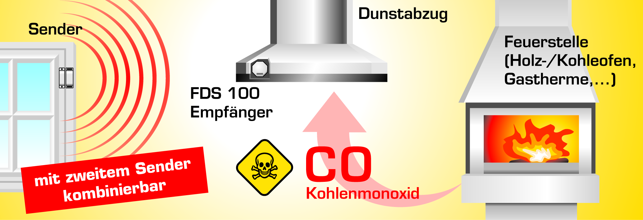
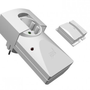
Das Abluftsystem kann nur dann benutzt werden, wenn das Fenster geöffnet ist und die dafür erforderliche Zuluft in den Raum einströmen kann. Ein Sender am Fensterflügel überwacht, ob das Fenster offen oder geschlossen ist, und übermittelt diese Information per Funk an den Empfänger. Dieser gibt die Stromzufuhr nur dann frei, wenn das Fenster gekippt oder geöffnet ist.
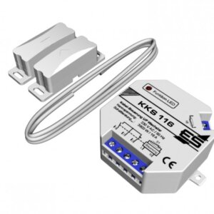
Beleuchtung unabhängig von der Fensterstellung: Die eine Leitung, die den Lüftermotor in allen Betriebszuständen sicher abschaltet wird aufgetrennt und mit dem Schließerkontakt (Klemmen 1 und 2) des FDS 100 wieder verbunden.
Ansteuerung eines Steuerkontakt: Einige Hersteller von Abluftsystemen stellen einen Kontakt zur Verfügung, der nur den Lüftermotor steuert, im Auslieferungszustand oft mit einer Drahtbrücke versehen. Diese Brücke wird gelöst und mit dem Schließerkontakt des FDS 100 geschaltet.
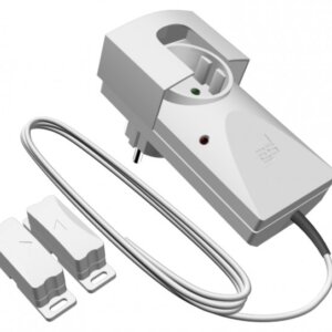
Zweites Fenster (ODER): Es muss mindestens ein Fenster geöffnet sein, damit das Abluftsystem eingeschaltet werden kann. Dazu wird das FDS 100 SET mit dem Zusatzsender FDS 098 oder FDS 098 L (Maße beachten!) für das zweite Fenster erweitert.
Zweites Fenster (UND): Es müssen zwei Fenster gleichzeitig geöffnet sein, damit das Abluftsystem eingeschaltet werden kann. Dazu werden zwei unabhängige FDS 100 SETs mit unterschiedlicher Codierung benötigt. Die Empfängerrelais müssen dabei in Reihe geschalten werden.
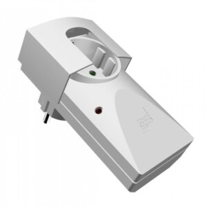
Zweiter Empfänger Zum bestehenden Set FDS 100 kann ein weiterer Empfänger (Einbau FDS 199 oder Zwischenstecker FDS 299) angesteuert werden. Sobald das Fenster geöffnet wird, schalten beide Empfänger das jeweilige Abluftsystem frei.
FDS 100 kombiniert mit Abgastemperaturwächter: Sobald die Abgastemperatur im Abgasrohr 40°C überschreitet, muss dabei das Fenster geöffnet werden:
FDS 100 kombiniert mit Funk-Abgastemperaturwächter: Sobald die Abgastemperatur im Abgasrohr 40°C überschreitet, muss dabei das Fenster geöffnet werden: FTX mit FDS 100 Set
Einsatzbereich
- Dunstabzugssteuerung
- Badlüftersteuerung
Leistungsmerkmale
- TÜV-geprüft mit DIBt-Zulassung Z-85.2-11
- Funkstrecken- und Batterieüberwachung
- Relaiskontakt 5 A, potentialfreier Wechselkontakt
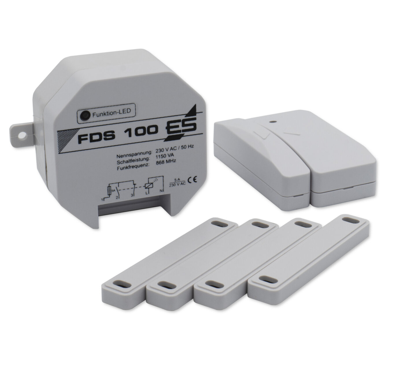
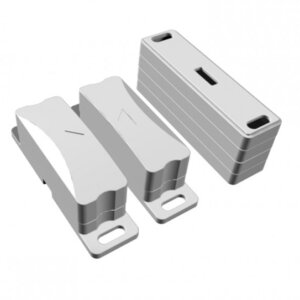
- 4 Distanzplatten für Magnet als Höhenausgleich zum Fenster
- erweiterbar mit Zusatzsender FDS 098 oder FDS 098 (L) (Maße beachten!) für zweites Fenster
- Beleuchtung der Abzugshaube funktioniert auch bei geschlossenem Fenster, wenn nur die Motorzuleitung geschaltet wird
- potentialfreier Kontakt zum Schalten von Motoren oder Steuerkontakten
- geeignet z.B. für BORA Professional Home In, Miele PUR 98, Miele KMDA7774
Lieferumfang
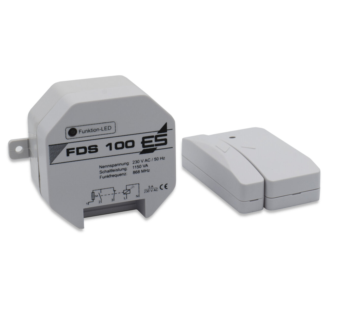
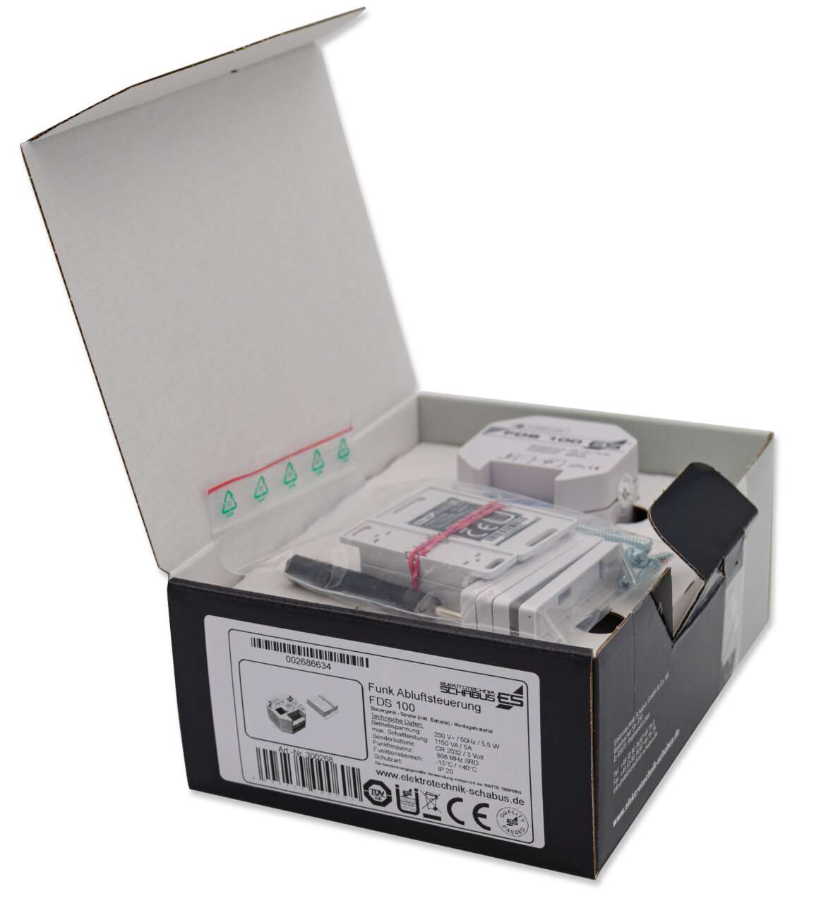
- 1x Empfänger
- 1x Funk-Magnetschalter (Sender und Magnet)
- 1x Batterie CR2032
- 4x Distanzplatten für Magnet
- Montagematerial
- Bedienungsanweisung
Farbe telegrau, Gehäuse des Senders auch auf Anfrage in verschiedenen RAL-Farben gegen Aufpreis erhältlich
Unser Gerät führt zyklisch einen automatischen RESET durch, danach muss für erneute Inbetriebnahme das Fenster einmal geöffnet werden (und ggf. vorher geschlossen werden).
Bei einer „normalen Nutzung“ von 1-2 Std. / Tag und optimaler Funkverbindung (kein Edelstahl oder sonstige abschirmende Materialien, idealerweise mit Sichtkontakt) ist bei einer frischen Markenbatterie mit einer Batterielebensdauer von bis zu 2 Jahren zu rechnen.
Anschlußbeispiele
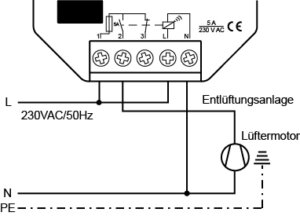 |
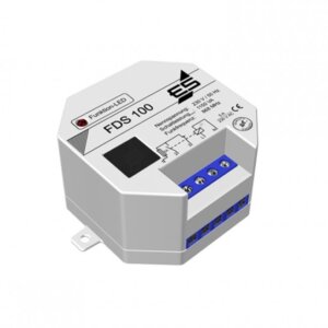
Anschlussbeispiel 1 Bei geschlossenem Fenster schaltet der Empfänger den Lüftermotor der Dunstabzugshaube oder Entlüftungsanlage stromlos. Der Empfänger kann Auf- oder Unterputz in einer Verteiler-, Schalter- oder Steckdose mit mind. 60 mm Ø eingebaut werden. Die seitlichen Befestigungslaschen am Empfänger können bei Bedarf weggebrochen werden. Der Einbau in die Dunstabzugshaube selbst sollte im Sinn einer guten Funkverbindung vermieden werden. | |
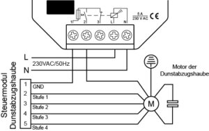 |
Anschlussbeispiel 2 Bei älteren Dunstabzugshauben mit mechanischer Gebläsestufenschaltung wird der Empfänger in die Lüftermotorzuleitung zwischengeschaltet, damit die Beleuchtung der Dunstabzugshaube unabhängig von der Fensterstellung funktioniert. | |
 |
Anschlussbeispiel 3 Einige Dunstabzugshersteller bieten externe Anschlussmodule zur separaten Ansteuerung des Lüftermotors an, z.B. BORA Professional Home In, Miele KMDA7774, uvm. Mit dem potentialfreien Relaiskontakt des FDS 100 Empfängers ist dies zu realisieren. Mit Anschluss an einen Steuerkontakt wird der FDS 100 auch BLDC-fähig. | |
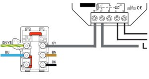 |
Anschlussbeispiel 4 Muldenlüfter von Bosch, Neff, etc. haben oft das Herdanschlussfeld mit eigenem Anschluss für den Lüftermotor. Die Brücke muss entfernt werden, es wird ein Leiter von einem der L-Anschlüsse abgezweigt und über die Klemmen 1 und 2 des FDS 100 auf den L1-Eingang des Herdanschlussfeldes geschaltet. | |
 |
Anschlussbeispiel BORA Basic BIA | BHA | …
|
Achtung! Metalle schirmen Funk ab * Hindernisse, vor allem Metalle, verringern die Reichweite im Vergleich zum freien Raum teilweise erheblich. Die tatsächliche Reichweite hängt immer von der jeweiligen Installation ab. Bei häufigeren Aussetzern im Betrieb, trotz frischer Batterie, ist oft eine schlechte Funkstrecke schuld. Die Entfernung zwischen Sender und Empfänger spielt dabei kaum eine Rolle. Halten Sie den Empfänger mind. 20 cm von der nächsten Metallfläche entfernt. Auch dicke Glasplatten, Ceranfelder, Küchenschränke mit Töpfen und Pfannen, sowie Wände und Decken schirmen die Funkwellen bestens ab und stören den zuverlässigen Betrieb. Richten Sie den Empfänger für eine gute Verbindung bei der Installation so aus, dass seine LED in Richtung des Senders „sieht“.
Technische Daten
| Betriebsspannung: | 230 VAC / 50-60Hz |
| Leistungsaufnahme: | ca. 7,6 VA |
| Schaltleistung (max.): | 1150 VA (700 W) / 5 A (Wechsler) |
| Funkfrequenz: | 868 MHz SRD |
| Reichweite: | bis zu 20 m im Freifeld* |
| Funktionsbereich: | -15° C / +40° C |
| Schutzart: | IP 20 |
| Batterie Sender: | CR2032 / 3 V |
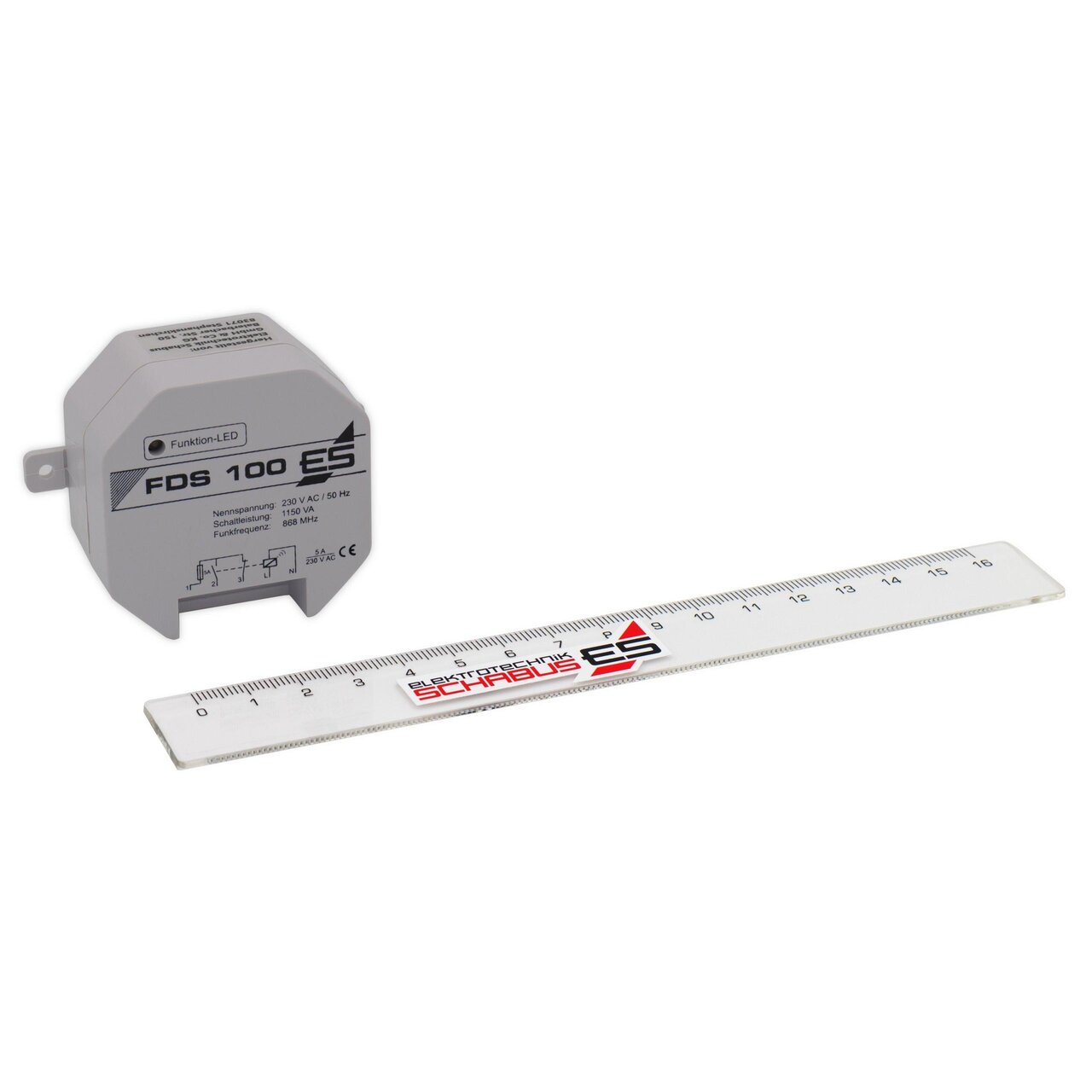
| Empfänger (HxBxT): | 53 x 53 x 31 mm |
| Sender (HxBxT): | 59 x 25 x 18 mm Gehäuse ab 04.2023 |
| Magnet (HxBxT): | 59 x 11 x 18 mm Gehäuse ab 04.2023 |
| Distanzplatte (HxBxT): | 59 x 11 x 5 mm Gehäuse ab 04.2023 |
Tipps zum Batteriewechsel
WEEE-NR.: DE91394868









Das Produkt ist gut, aber die Betriebsanleitung ist verbesserungswürdig